- Part Detail
- CLICK TO VIEW
TRIUMPH PLATES - Browse Original Triumph Catalogue Plates
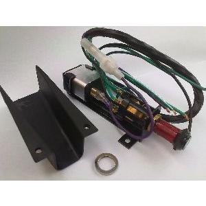
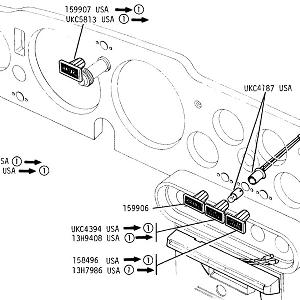
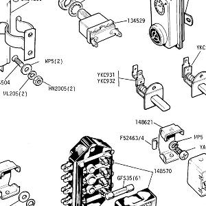
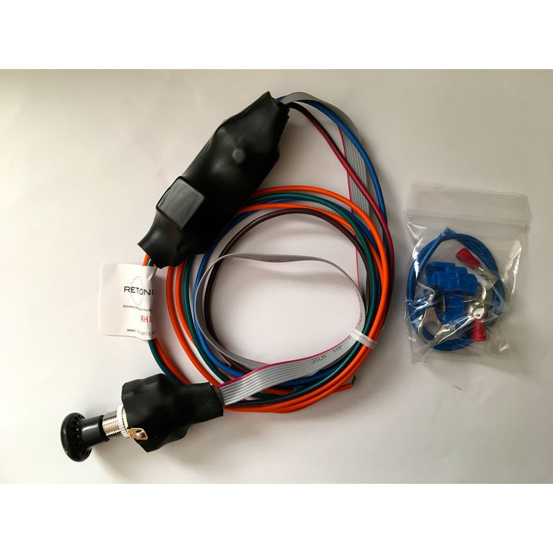
Not recommended as GSS159-1 is a superior solution. Hazard warning switch kit. This compact kit comes with all the components and the pull switch all mounted in one carrier. The illuminated pull switch operates the hazard facility but this kit will only work with -ve earth cars.
An alternative unit GSS159-1 is available (both -ve and +ve earth) with a separate switch and module, useful where space is limited on the dashboard making GSS159 difficult to fit.
Fitting Tips
The following connection references for fitting GSS159 to a TR may be useful as a guide : -
Hazard Unit |
Main Loom |
|
| Green/White |
Green/White |
|
| Green |
Green/Red |
|
| Green/Purple |
Terminal L on standard flasher unit |
|
| Green/Purple |
Green/Brown which is disconnected from Terminal L on standard flasher unit | |
| Purple |
|
|
| Black |
- ve earth |
These additional notes may help
1. Connect the purple wire to a suitable 12v permanent live source. A spare terminal may be found on the fuse box or direct to the
permanent live side of the starter solenoid. Connect the black wire to a suitable body earth.
2. Disconnect the wire that goes from the ignition switch to the live terminal on the indicator flasher unit (this wire is usually green
and connected to the flasher unit terminal marked 'B'). This terminal is only live when the ignition is switched on.
3. Identify the green/purple wires on the Hazard Light Switch. Connect one green/purple wire to terminal 'B' on the flasher unit
and the other green/purple wire to the feed wire for the indicator flasher unit.
4. Locate the indicator wiring connectors on the car. These are the connections where the wires from the indicator switch join the
main loom, normally green/white and green/red colour codes.
Connect the green/white wire from the hazard switch to the green/white circuit and connect the green wire from the hazard
switch to the green/red circuit.


