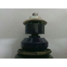
- Part Detail
- CLICK TO VIEW
TRIUMPH PLATES - Browse Original Triumph Catalogue Plates
DAMPER CONVERSION KIT rear SPHER HQ TR4A-6

Part No:
RTR3003RJ2K
Price
£692.48
Price Ex VAT @ 20%
£577.07
IN STOCK This part is immediately available
TR4AIRS-6 Rear damper conversion with PTFE lined Spherical Bearing Lower Joints
TR4AIRS-6 Rear damper conversion kit employing Telescopic Adjustable dampers fitted inside the rear springs, where Triumph should have put them! The kit comprises 2 dampers with SuperPro polyurethane upper bushes and Spherical Bearing Lower Joints plus all the necessary brackets and fittings. These spherical bearing lower joints are employed to give the best fast acting damping ideal for discerning road car drivers as well as track day and competition us. The lower spherical bearings are constructed with a PTFE lining to limit the transmission of noise.
The RevingtonTR damper inside coil rear suspension set-up gives better spring control than the original arrangement resulting in greatly improved road holding. The dampers are adjustable to suit your own preferences and have a longer useful life. When fitted correctly the bump and rebound travel is the same as standard.
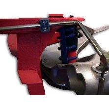
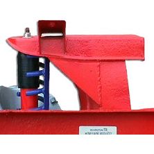
With the Dampers fitted inside the rear springs, ground clearance and wheel clearance is maintained ensuring no interference with the tyres under compression. This is the definitive kit - not to be confused with inferior set up's with brackets off the chassis or the inner bodywork.
There is no need to change the trailing arm (aluminium part) that supports the car as the system bolts to it. 6 holes are drilled through the trailing arm to support the damper brackets.
It is not necessary to dismantle the car In order to install the damper kit other than to remove the old springs and dampers. Revington TR recommends taking off the trailing arms though to make the job easier and to change the trailing arm bushings for new SuperPro polyurethane ones. Order SPF0077K. The job takes a little time to complete but it is not a difficult job for a competent mechanic.
We are flattered by the constant stream of positive feed back we get from customers with this kit fitted, especially when fitted as part of our integrated suspension packages.
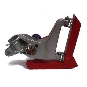
A limited amount of welding is required to the chassis to add mid steel strengthening gussets and top support plates to the spring turret. The lower bracket (consisting of a top and bottom part made from mild steel zinc plated) is secured to the trailing arm with nuts and screws.
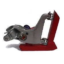
Four images of the various lower arrangements are attached. The two spherical bearing arrangements are similar to look at but differ in the quality and construction of the bearing itself.
Benefits: -
·The original lever arm dampers are an old design, and almost certainly were carried through from TR2 to TR6 on cost grounds alone. Changing to telescopic dampers brings the ability to adjust the damper to suit individual driving style and all the technological benefits of a more modern design.
·The original lever arm dampers have a link arm with rubber joints at both ends. These rubber ends allow wheel movement before the damper comes into effect resulting in a bouncy ride. These links are eliminated when our telescopic damper conversion is installed.
·Lever arm dampers are prone to coming loose as the action of the lever twisting in the body applies constantly reversing loads on the mounting screws.
·By putting the damper inside the spring all the forces are right where they should be; coincidental with the spring the damper is trying to control. Anywhere else is a compromise.
·Revington TR developed this rear damper conversion in conjunction with a reputable damper supplier and specialist damper builder. The installation design was undertaken by Neil Revington whilst the damper design and all its internal valve setting was specified by the damper specialist who had the benefit of the use of our TR5 for several weeks of testing and fine tuning of the system.
·All other telescopic damper kits on the market utilise a damper sat inside the wheel arch. Some of the disadvantages of these systems are; -
Similar twisting motion as lever arms, when the brackets are bolted to the original mount.
The space taken by the damper in the upper wheel arch is often the same space required by the tyre on full bump, resulting in the tyre rubbing on the damper and brackets.
As the damper now sits inside the springs and acts as a rebound stop, the damper determines the travel. The bump stop acting between the upper face of the trailing arm and the tower inside the wheelarch still acts as the bump stop.
As the damper now sits inside the springs and acts as a rebound stop, the damper determines the travel. The bump stop acting between the upper face of the trailing arm and the tower inside the wheelarch still acts as the bump stop.
These adjustable dampers can be set to control a standard spring right up to ones with a rate of 650lb.


